The Dreaded Drivers Door Module Part Numbers

That is just so damn strange. Yea, you clearly have something going on. I guess my question would be if there is any way to load your as built file even if the module does not show in the scan, like can you add the module?

You have tried with the car fully running too, not just with power on?
 
Last edited:
That is just so damn strange. Yea, you clearly have something going on. I guess my question would be if there is any way to load your as built file even if the module does not show in the scan, like can you add the module?

You have tried with the car fully running too, not just with power on?
That's on the list for tonight/tomorrow, right after I verify both 12 V hot leads (only checked one, then looked at the connector tonight and realized there are two on C501a) and the grounds. If those check good, I guess it could be the bus wires, but from what I know about busses, if there is a break, more than the DDM should have stopped working.
 
Progress! Sure enough, the 2nd VT/LG wire on C501a had no voltage at the connector! So I started looking at it, and sure enough, a few inches from the connector, someone had shaved off a tiny piece of insulation to no doubt probe it. I checked voltage there and it showed 5V more or less, but was jumpy. So, someone who probed that with a power light got a positive reading and likely never checked it with a multimeter.

Inspection of the wire showed no breaks in the places I could see. Checked the fuse for it and it was fine, and had power. So, I cut that wire about 6" from the connector and jumpered directly to the fuse for it on the fusebox. Now I have full 12V in the connector.

Plugged in the DDM, but nothing worked. So, tried the FORScan, and got the result below! Now I just need to find the break in the wire and repair it. Tomorrow's project is to try to get into the conduit between the door and the body, the most likely spot for that wire to be broken. Once I have that done, I can load the As-Built to the DDM and hopefully be GTG!

IMG_5789.webp
 
Update as of this morning:
I have four DDMs that will read on FORScan. One of them, S/N 73709 running software version v4 2002-08-22, has different as-built codes from the other three and will not program my remote. It is also showing code B1526, the only one of the three with that code. As-built banks are as follows for it: 8000 0000 FF20.

As-built banks for the other three modules are C000 0000 FF60. They are running SW version v4 2003-02-06. I successfully programmed my remote for all three of those modules, and all three are throwing code U1135, which I am gathering means the battery is weak. Got it on a charger, but that doesn't seem to be helping. Guess I know what's next.

Now, while the remote keyless works with these DDMs, nothing else does. Seat and mirror adjustments are still dead. One of them is throwing additional DTCs B1322 and B1566. So, back to trouble-shooting I go........

That's great! Just to confirm you said you programed remotes to all the DDM but did you also program them with your as built data?
 
That's great! Just to confirm you said you programed remotes to all the DDM but did you also program them with your as built data?
When I try to load the As-Built file, FORScan comes back and tells me that there is no As-Built file for this module in the data from Ford, which is consistent with my earlier post where I noted the screen capture from the Motorcraft site did not show DDM data. FWIW, one of the working modules is from an '04 Town Car Ultimate like mine.
 
When I try to load the As-Built file, FORScan comes back and tells me that there is no As-Built file for this module in the data from Ford, which is consistent with my earlier post where I noted the screen capture from the Motorcraft site did not show DDM data. FWIW, one of the working modules is from an '04 Town Car Ultimate like mine.
You don't necessarily have to load the as built file if you can figure out the hex value for your as built ddm file then you could just put that hex value directly in forscan and overite the previous value. Assuming forscan let's you get that far.
______________________________

Help support this site so it can continue supporting you!
 
You don't necessarily have to load the as built file if you can figure out the hex value for your as built ddm file then you could just put that hex value directly in forscan and overite the previous value. Assuming forscan let's you get that far.
I think I could do that, but I don't have any reference to go by. All of the data in the Panther document is for later Panthers which won't interchange with the '03-'05 cars. I may try your settings on one of the modules.
 
Edit to above: I have '03 Cartier settings to try from a post above. I'd like to see the settings for @raiderfan247365 and @wolf_walker since your cars should have interchangeable DDMs.

Just went out and reprogrammed the '03 DDM S/N 73709. The only setting I could change was to enable the horn chirp. This changed its banks from 8000 0000 FF20 to C000 0000 FF60, which is identical to the other DDMs' banks.
 
Last edited:
Edit to above: I have '03 Cartier settings to try from a post above. I'd like to see the settings for @raiderfan247365 and @wolf_walker since your cars should have interchangeable DDMs.

Just went out and reprogrammed the '03 DDM S/N 73709. The only setting I could change was to enable the horn chirp. This changed its banks from 8000 0000 FF20 to C000 0000 FF60, which is identical to the other DDMs' banks.
I can post mine on Sunday
 
I can post mine on Sunday
That would be great just to have for reference.

Having said that, I think I have it figured out. That same LG/VT wire that was bad for the DDM is also the hot lead for the seat, lock button, and mirror controls. I've just ordered some 20 gauge wire, should have it all wired up tomorrow.
______________________________

Help support this site so it can continue supporting you!
 
Last edited:
Wonder what happens when a feature is missing, like mine has a sunroof but all the other options are the same as yours. When it cools off in a bit I'll fire up forscan and see if I can get that for you.
 
Well, the plot thickens. There are 7 connectors in the door that the LG/VT wire feeds. So, all I need to do is find that wire back in the drivers side footwell and jumper from that to the point where the 7 wires meet in the door harness and we should be GTG, right? Nope, Ford made things more complicated than that. Pic below is the splice down in the driver's door. Sure enough, 7 come out, BUT there is not one LG/VT coming in, there are four of them! OK, so maybe only one is dead. I hook up the battery, and three of them have no voltage, one is in the 7V range. A check at the junction box shows the full 12.7 V available. Why are there four, and what else are the connected to? Where is that 5V leaking too? Wiring manual isn't much help. It just shows a one-into-seven splice. There are earlier splices to connect to the adjustable pedal switch, which is on the dash. Need to check voltage on it.

IMG_5847.JPG

So, getting back to the manual, it says everything goes through connector C238, right down behind the e-brake. There are two alternative wire configs for that connector, C238 and C2026. EDIT: I found another error in the wiring manual - there's a reason that there are several blank forms for error reporting from techs in the back of these manuals. Previous error I found was a misnumbered connector pin. As you can see in the diagram below from the manual, C238 is supposed to be the middle of three connectors mounted on a plastic bracket. It's not. Its position is actually reversed from C237. On to continued diagnosis in my next post....


Screen Shot 2022-09-18 at 3.50.35 PM.webp
 
Last edited:
BTW, the hot lead should be LG/VT, NOT VT/LG as I originally typed it. I guess I'm having late onset dyslexia too from looking at the wiring manual for so long! I corrected it in all but one of my posts, which the board will not let me edit for some reason.
 
The connector views for C238 in the 2003 & 2004 WDs are identical. Both show LG/VT on pin 12. And, yes, the connector you pictured certainly does look like C238.

All below page numbers are from the Service DVD.

On pg 13-17 in Power Distribution, the LG/VT wire does show on pin 12 of C338 with a tap earlier (S291) to the Pedal Switch. After C238, on that diagram, S511 is 1 in, 9 out. 3 of the 9 go to items outside of the driver's door. I know these numbers don't match exactly what you have but items outside of the driver's door on this circuit would explain the "some to the door and some not" in S511.

On pg 57-1 in Driver Door Module there is no mention of C238 in the LG/VT wire. Maybe the LG/VT wire doesn't actually go through C238.

I have attached those two WD pages.

Checking voltage at S291 is a good next step.

Good Luck!
______________________________

Help support this site so it can continue supporting you!
 

Attachments

  • 2004 Town Car WD Page 13-17.webp
    2004 Town Car WD Page 13-17.webp
    70.5 KB · Views: 4
  • 2004 Town Car WD Page 57-1.webp
    2004 Town Car WD Page 57-1.webp
    80.9 KB · Views: 4
The connector views for C238 in the 2003 & 2004 WDs are identical. Both show LG/VT on pin 12. And, yes, the connector you pictured certainly does look like C238.

All below page numbers are from the Service DVD.

On pg 13-17 in Power Distribution, the LG/VT wire does show on pin 12 of C338 with a tap earlier (S291) to the Pedal Switch. After C238, on that diagram, S511 is 1 in, 9 out. 3 of the 9 go to items outside of the driver's door. I know these numbers don't match exactly what you have but items outside of the driver's door on this circuit would explain the "some to the door and some not" in S511.

On pg 57-1 in Driver Door Module there is no mention of C238 in the LG/VT wire. Maybe the LG/VT wire doesn't actually go through C238.

I have attached those two WD pages.

Checking voltage at S291 is a good next step.

Good Luck!
Thanks @etinpa , see my edit above, I found an error in the wiring manual.
 
I checked continuity to C2089 (adjustable pedal switch) and C238 (connector down in the kick panel referenced above), both are good. The wires are dead, and possibly shorted, somewhere past C238. I jumpered from the junction box out to the seat controls on the door, but the seat still did not move. Guess which wire comes off of C238 and also goes under the carpet to the seat module? Yep, the LG/VT wire again. I bet the Ford engineer's name who came up with this was Sauron Jr. One Wire to Rule Them All. But I digress.

So what that tells me is that LG/VT dies somewhere just past C238, before the splice out to the seat, and also, to the power trunk. Did I mention One Wire to Rule Them All?

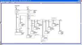
Below is the power distribution diagram with my plans and notes to solve this. I'm going to cut LG/VT before C238 because that's the only place I can get to it. From there, I'll do a 1->2 wire split with GR going out to the door, an WH splitting again under the dash with RD to the pass side lock (hopefully I can find LG/VT going to the pass side lock switch under the dash on the driver's side to splice into) and WH down to the floor where it will split again into BL for the seat and Y for the trunk. This is the little diagram at the top under Note Wire Colors.

Everything in the door is noted by a sort of pink check mark. I can get them all with the one GR wire out to the door. I'll have to do 1 -> 2 -> 4 -> 7 wires the way Ford did it to keep the splices manageable. The 4->7 piece is already in place as you can see from my earlier pic. The other splits above take car of everything not in the door, which is outlined in yellow (Ignore the small yellow boxes around the C501 DDM connectors).

My guess is that this will take me the better part of a week to do in my spare time. :( I'll let you know how it all worked out.....any constructive feedback on the plan is appreciated.

PS - does anyone know how to get that heavy black plastic conduit apart that runs under the carpet between the seat and the door? It would be nice to put my splices for the seat and trunk in there.

IMG_5853 copy.jpg
 
Last edited:
It sounds like you're getting way too involved in this and plan to replace wires that are already OK.

Step one should be to troubleshoot the low voltage issue. There's likely a bad connection that's causing the voltage drop. If the fuse is blowing next troubleshoot the short and isolate it to one wire (this may involve separating the splices).

I'll bet once you find and fix these issues you'll discover that most of the wires you mentioned are actually OK.
Appreciate the thoughts @etinpa . That's actually about what I set out to do. Note that there are no fuses blowing. The problem is that I have now touched every connector and every part of the wire that I can get to without removal of the door and dash. The bad spot in the wire is in an area I can't get at without major surgery, somewhere between where the massive harness curls back on itself behind C238 and goes through the body and the point where there are four LG/VT wires in the door. This rewiring job is what I'm left with.

After some further thought though, and noting that three of the four leads in the door gave very similar readings while one appeared to be attempting to carry voltage, I wonder if the other three leads are the leads back to the seat, trunk and pass side door? I'm going to check that out tonight if I can. That would vastly simplify my wiring task. Doesn't make a bit of sense on the surface to have done it that way, but Ford works in mysterious ways.
 
Back
Top