2024 Nautilus software and battery issues

That won’t download on mi iPhone … should it?
Hi LHB. I was able to download it on my iPhone. Downloaded to the “Download” folder and viewed there.

Good luck.
 
Hi LHB. I was able to download it on my iPhone. Downloaded to the “Download” folder and viewed there.

Good luck.
Found it … once I found the ‘download’ folder there they were. Thanks bbf2530.
 
'
I attach my noco under the hood. The same connection method recommended to jump the Nauti.
FYI … this is what I got from NOCO … which is why I got to the battery and connected to its + and - posts.

“If you have both positive AND negative remote posts, you could connect to them, but if it is only a positive remote post, that is for jump starting only and not battery charging and you would need to directly connect to the battery to charge it.

You can use the GC002 1/4" eyelets or GC008 3/8" eyelets to mount to the battery. Then when you need to charge, you can just hook the charge to the cable.

Regards,
Chris G
NOCO Customer Support Supervisor”
 
Last edited:
Interesting comment. I have no issues charging the battery from under the hood. I use DVM to check voltages at various stages with and without the charger attached. For example, when light is solid green (not slow pulse) the voltage is 12.6 to 12.7 volts.

I assume the comment is because some setups may prevent charging.
 
'

FYI … this is what I got from NOCO … which is why I got to the battery and connected to its + and - posts.

“If you have both positive AND negative remote posts, you could connect to them, but if it is only a positive remote post, that is for jump starting only and not battery charging and you would need to directly connect to the battery to charge it.

You can use the GC002 1/4" eyelets or GC008 3/8" eyelets to mount to the battery. Then when you need to charge, you can just hook the charge to the cable.

Regards,
Chris G
NOCO Customer Support Supervisor”
While I respect his recommendation, I wonder if you could ask him about the comment from @Starfish about including the BMS in the charging path. I think it might confuse the BMS if the battery SoC changes significantly without it's knowledge.
 
Thanks for your input Starfish …
2 questions:
1. Why?
2. Where is the BMS?
Thanks.
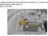
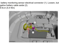
As far as where, this image shows the battery monitoring sensor (1) attaching to the battery feed just near the post. Rather than connect to the post at position (2), connect to the bolt at the position indicated by the red arrow.

1000007625.png

The reason why is that this lets the current pass through a shunt resistor at that connection point (between the arrow and (2)). The vehicle's BMS will then know how many Ah of charge you supplied to the battery external to the power system. If you connect directly to (2), you bypass the monitoring system and the BMS may not manage current flow properly based on the battery's SoC.
 
I assume if you bypass the BMS once you complete the charge you should reset the BMS. I forget the sequence.
 
Where do you connect negative with the above diagram?
 
Where do you connect negative with the above diagram?
Bolt at red arrow.

Alternatively you can try the jump points under the hood. But if you want to heed the recommendation of NOCO, then I personally would use the point at the red arrow.
 
Last edited:
/' I
Bolt at red arrow.

Alternatively you can try the jump points under the hood. But if you want to heed the recommendation of NOCO, then I personally would use the point at the red arrow.
Does anyone know nut & thread size to piggyback Genius5 leads to the + and - connections?
 
/' I

Does anyone know nut & thread size to piggyback Genius5 leads to the + and - connections?
Someone may correct me, but looking at parts, it appears to be an M8x1.25 nut. If you're using an SAE spade lug or ring terminal you could probably get by with a 3/8".
 
Someone may correct me, but looking at parts, it appears to be an M8x1.25 nut. If you're using an SAE spade lug or ring terminal you could probably get by with a 3/8".
1722026228457.webp
I’m referring to the connection point indicated by red arrow…
 
View attachment 21712
I’m referring to the connection point indicated by red arrow…
I understand. I can't tell unless I were to access it directly. That connection point is part of a cable assembly and not specified separately. I believe it's an M8 nut, but can't confirm although @Steve_C seemed to think so also.

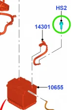
However, the cable leads directly to the vehicle body where it's bolted down with an M8 bolt. That would be equally as good. (Bolt in green circle below.) In this case, use the NOCO GC008 3/8" option.

Screenshot 2024-07-26 155708.png
 
Last edited:
I understand. I can't tell unless I were to access it directly. That connection point is part of a cable assembly and not specified separately. I believe it's an M8 nut, but can't confirm although @Steve_C seemed to think so also.

However, the cable leads directly to the vehicle body where it's bolted down with an M8 bolt. That would be equally as good. (Bolt in green circle below.) In this case, use the NOCO GC008 3/8" option.

View attachment 21715
I would go to an ACE or True Value Hardware, or the like, and pick up an M8 and an M10 to cover bases! They sell them loose, under 50 cents apiece!
 
LHB's recommendation for connecting the negative lead at the "Red Arrow" on diagram is the location confirmed by my dealer.
 
Back
Top