Wiring diagram CHT PCM

thomas.melbye

Junior Member
Joined
Jan 30, 2018
Messages
21
Reaction score
1
Points
3
Location
Sweden
My Lincoln
Town Car 1999 120" limo
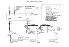
Having an issue with temperature sensor and gauge.
Gauge can show 0, normal or boiling temperature when starting the car cold. Engine can be at running temperature and gauge showing 0 or normal or boiling.
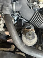
When driving it can jump to boiling, cooling warning flashes and car goes to limp mode. Temperature on thermostat housing, hoses and radiator is within normal range.
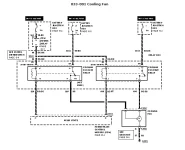
Also having issue that coolant fan started running continuously.

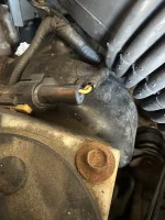
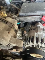
Have replaced cht sensor and coolant sensor on the bridge without any change.

Suspecting that the issue is within the wiring harness.
Would need to measure continuity on the cables to see if there is a short or break somewhere.
Alternatively bypass most of the harness and run new cables for the sensors.

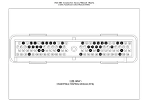
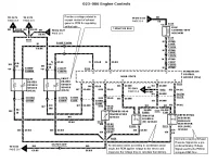
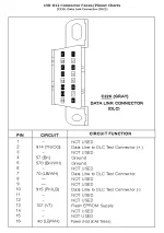
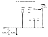
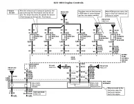
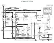
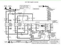
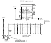
Does anyone have a wiring diagram for this stretch of harness and what pins it should be at on the ECU/PCM.

Not a mechanic but know my way around a spanner
 
The CHT sensor is not connected to a gauge. The CHT provides data to the PCM. If too hot this will cause the PCM to trigger limp mode.
There are at least 2 other engine heat sensors.
One for the instrument mounted gauge if vehicle is supplied with one. The wiring for this does not go through the PCM.
One for the radiator fan(s). The PCM may control the fan operation. (except when the AC compressor is on) And if so, it is done with a separate engine coolant sensor.
May be one for the HVAC system

This statement, "When driving it can jump to boiling, cooling warning flashes and car goes to limp mode."
seems to me as there is air in the cooling system. Rapid changes in the temp gauge could be from the sensor contacting air or coolant. Air in the cooling system is a common issue with the modular engine family one a piece has been replaced that opens the system. Some 4.6l engines of the 1990s have an air bleed in the metal crossover pipe close to the alternator.

To rule out actual coolant issues, use an infrared thermometer on parts of the engine specifically cooling system related. Intake manifold that has coolant. Thermostat housing. Upper radiator hose. Water pump.

Down the electrical rabbit hole -
Several years ago it was common to find wiring diagrams on the net. Not so much. Many are protected. However, someone here may have one to post. I do not. The hard copy of the entire vehicle's wiring can be found on eBay for under $15USD. Thomas, I suspect you are not in the states, because no one in the states uses a spanner. BTW not sure what a bridge is doing under the hood of a car, but I will take your word for it.

Action
 
Here are some wiring diagrams that may be helpful.

The attachment with "SCP" in the filename includes a list of signals received via the network. "Engine Coolant Temperature" is listed there and elsewhere in the Service Manual but I cannot find the ECT sensor in the wiring diagrams so I can't tell you what module it connects to.
 

Attachments

  • 1999 Town Car C185 Pin Out.webp
    1999 Town Car C185 Pin Out.webp
    35.9 KB · Views: 4
  • 1999 Town Car WD CHT.webp
    1999 Town Car WD CHT.webp
    60.9 KB · Views: 5
  • 1999 Town Car WD Cooling Fan.webp
    1999 Town Car WD Cooling Fan.webp
    28.8 KB · Views: 4
  • 1999 Town Car WD SCP List.webp
    1999 Town Car WD SCP List.webp
    48.8 KB · Views: 4
The CHT sensor is not connected to a gauge. The CHT provides data to the PCM. If too hot this will cause the PCM to trigger limp mode.
There are at least 2 other engine heat sensors.
One for the instrument mounted gauge if vehicle is supplied with one. The wiring for this does not go through the PCM.
One for the radiator fan(s). The PCM may control the fan operation. (except when the AC compressor is on) And if so, it is done with a separate engine coolant sensor.
May be one for the HVAC system

This statement, "When driving it can jump to boiling, cooling warning flashes and car goes to limp mode."
seems to me as there is air in the cooling system. Rapid changes in the temp gauge could be from the sensor contacting air or coolant. Air in the cooling system is a common issue with the modular engine family one a piece has been replaced that opens the system. Some 4.6l engines of the 1990s have an air bleed in the metal crossover pipe close to the alternator.

To rule out actual coolant issues, use an infrared thermometer on parts of the engine specifically cooling system related. Intake manifold that has coolant. Thermostat housing. Upper radiator hose. Water pump.

Down the electrical rabbit hole -
Several years ago it was common to find wiring diagrams on the net. Not so much. Many are protected. However, someone here may have one to post. I do not. The hard copy of the entire vehicle's wiring can be found on eBay for under $15USD. Thomas, I suspect you are not in the states, because no one in the states uses a spanner. BTW not sure what a bridge is doing under the hood of a car, but I will take your word for it.

Action
Thanks for your answer.


I was somewhere told that it was called a bridge.
It goes from the thermostat housing over to the right side of the intake manifold.

It was said that this car doesn’t have a regular coolant temperature sensor, but there it is.
And it’s behind the alternator

There might be air in the system, but with a cold car that I haven’t cranked shouldn’t show boiling.
It’s not the usual self-test of the gauge, it’s erratic and jumps between nothing, normal, boiling, nothing, boiling and so on.

Same goes for driving with the engine at operating temperature. It can dump down to zero and then jump to boiling.

I have used an infrared thermometer in the places you mentioned and it’s all within normal temperature. The thermostat is opening as it should.

I think the issue is electrical.

Unfortunately, some idiot tried replacing the OBD port and has mixed up all the cables. Haven’t been able to figure out what goes where.


I’m not in the states. If I were it would be some mechanic around that would be able to fix this.
Over here there is no dealership for Lincoln or US Ford and most mechanics do European or Asian cars.
Some do American cars, but those are from the 70’s or older.
Classic American cars are kind of popular here.
______________________________

Help support this site so it can continue supporting you!
 
Thanks for the reply.

I would agree based on what your wrote regarding the IR thermometer, the issue appears to be electrical.
The work done by the PO (previous owner) has really handicapped the diagnosis.

Given that situation, the diagrams etinpa has posted are rather generous.
However, I believe you may want the entire diagram for the vehicle. Buy one listed on eBay might be prudent at this point.
Once correctly wired the OBD port then becomes your friend as far as diagnosing electronic power train controls.
That may be the issues with the concern based on this thread. Or maybe not. And you KNOW this concern exists.

My strategy for repairs on any vehicle
Work (repair) from the known concerns to the unknown concerns
Repair the easy items first
Also repair the lower cost items first

Good luck my friend across the pond as they say.

Action
 
Attached pin out with wire colors for 1999 Town Car Data Link Connector (OBDII port).
 

Attachments

  • 1999 Town Car DLC Pin Out.webp
    1999 Town Car DLC Pin Out.webp
    29.8 KB · Views: 9
Attached pin out with wire colors for 1999 Town Car Data Link Connector (OBDII port).
Thanks etinpa.


Got a little confused with one of the colors

Pin 7 Circuit 70 LB/WH
Pin 16 Circuit 40 LB/WH

Would it be that pin 16 is hot at all times and that pin 7 is not?
 
Pin 16 is hot at all times from Fuse 23
Pin 7 is a network connection to the restraints module

I'm surprised they used the same color for such different applications
______________________________

Help support this site so it can continue supporting you!
 

Attachments

  • 1999 Town Car WD Network.webp
    1999 Town Car WD Network.webp
    19.1 KB · Views: 5
Attached pin out with wire colors for 1999 Town Car Data Link Connector (OBDII port).
Appreciate your help and patience with me… 🙏


I tried connecting everything but still no luck.

I guess the chart shows the connector from the front, not the back where all the cables enter.

I have power but I’m not able to get any link with the OBD.

I have tested the PCM in another car and there is link there. Suspect some cable problems.
I would need a oscilloscope to see if I have any data going through the cables.


I also tested the connection going to the CHT sensor. There is a connector conveniently placed near the thermostat.

On the yellow cable I get 5.08v on the cable when not connected. Nothing on the other one.
When connecting it to the sensor I see a drop to 2.44v and still nothing on the other cable.

If I understand the diagram correctly the yellow cable goes to the PCM. But why would it be voltage going out that way?

And could it be that there is no power going into the sensor and therefore not working as it should?

Where does the sensor get its power from?
I see a junction called S123 (if I read this diagram correctly). Is this a connector somewhere?
And 359 is the feed to several sensors. Is there a fuse that could be blown?
Is there a easily accessible place to check this?

And in the worst case, what would happen if I tried adding 12 volts to this line?


Really not good at explaining this, but I hope you understand.


Me confused…:confused:
 
The operating voltage for the electronic engine (powertrain) controls is 5 volts. This is done so during times of low battery voltage, it is still possible to have a running engine.

Do not add 12 volts to any electronic engine control piece.

Not sure how you are measuring voltage drop at CHT. If this is current through the CHT on the return side, then it is normal. That current goes to the PCM. If there is no current at the PCM, there is an issue with wiring from the CHT to the PCM.

A "junction" labeled with a "S" is a splice. No connector. It is a permanent connection. And will be wrapped in the harness.
If it were a connector it would be labeled with a "C".

Action
 
Last edited:
I see a junction called S123 (if I read this diagram correctly). Is this a connector somewhere?
And 359 is the feed to several sensors. Is there a fuse that could be blown?
Is there a easily accessible place to check this?

S### is the designation for a splice in the wiring harness where C### would be a harness connector designation(usually a male/female plug and receptacle).

Circuit 359 looks to be the power source for the sensors and likely fused. You would need to trace back to page 23-5 to follow to the source.
 
DO NOT put 12 volts on that line! As Action said, it's a 5 volt sensor circuit. If you introduce a higher voltage something will likely smoke!

It will take a bit of time but I'll go through your post and answer everything I can.
______________________________

Help support this site so it can continue supporting you!
 
I pasted your entire post here in green so I can embed my responses...

Appreciate your help and patience with me… 🙏
No problem... we'll work through it.

I tried connecting everything but still no luck.

I guess the chart shows the connector from the front, not the back where all the cables enter.

Yes, the drawing is of the connector face.
I have power but I’m not able to get any link with the OBD.

I have tested the PCM in another car and there is link there. Suspect some cable problems.

Or the OBDII connector wiring is still not correct??
I would need a oscilloscope to see if I have any data going through the cables.
Yeah, probably... but you can check for voltage on the ISO and SCP busses. Voltage to ground on the following pins of the OBDII connector (driver's door open so the communication is awake but key out and off). Readings from a 2005 Town Car:
Pin 7=0.36V
Pin 10=5V
Pin16= 12V (battery power)

You're likely going to need to get communication to final troubleshoot your other issue.


I also tested the connection going to the CHT sensor. There is a connector conveniently placed near the thermostat.

Is this connector in addition to the one that actually connects to the CHT? If so,weird thought... maybe the wiring harness was designed to accept EITHER CHT or ECT (the wiring diagrams do NOT show this but...). Either way, you should NOT connect two sensors to the same PCM sensing wire.


On the yellow cable I get 5.08v on the cable when not connected. Nothing on the other one.
When connecting it to the sensor I see a drop to 2.44v and still nothing on the other cable.

That could be correct. The GY/RD wire goes back to the PCM along with a bunch of other sensors to provide the zero volt reference for the sensors. The YE/LG wire gets 5 volts from the PCM when not connected. When connected, the sensor pulls that voltage down. The final voltage of the YE/LG wire is the CHT signal to the PCM.

If I understand the diagram correctly the yellow cable goes to the PCM. But why would it be voltage going out that way?

Actually, the YE/LG wire comes FROM the PCM (see signal description above).

And could it be that there is no power going into the sensor and therefore not working as it should?
It looks like it DOES have power (see signal description above).


Where does the sensor get its power from?
I see a junction called S123 (if I read this diagram correctly). Is this a connector somewhere?

S123 is a splice. It's the common zero volt signal for a bunch of sensors.
And 359 is the feed to several sensors. Is there a fuse that could be blown?
Unlikely... see above
Is there a easily accessible place to check this?

And in the worst case, what would happen if I tried adding 12 volts to this line?

The "magic smoke" could come out... with our luck, from something expensive! :eek:

Really not good at explaining this, but I hope you understand.

You're doing fine!

Me confused…:confused:

Yeah, me too! Keep at it!
 
Thanks again.
Not going to play with 12v..... o_O

Going to have a go at det OBD later today. (probably, maybe)

There is both a CHT and ECT sensor on this car and both are connected.
CHT sensor is behind the alternator and the ECT sensor is beside the alternator on the other side.

Both sensors have been replaced.


I measure the ECT sensor on the back of the connection that is placed behind the Power steering reservoir. (see photo).
On the yellow cable I have 5.08v when not connected and that voltage reduces to 2.44v when I plug the connector in. It’s the yellow cable that drops in voltage. The red cable is still 0.

I asked ChatGPT and I think I might be on to something…

“If you’re chasing a fault, and one of these wires is open or shorted to chassis or 12V, you may see erratic temp readings or codes like P1285 (Cylinder Head Overtemperature) or P0117/P0118 (ECT circuit low/high input).”

That is exactly what I’m seeing.

The question is now how to easily address this issue.

The fault could be on the signal side to the PCM. A solution could be to replace the wire from the sensor PCM (splice it as close as possible. And maybe replace the cable going to common zero from junction S123 (if it’s possible to find that).

That way I eliminate if the cable is open somewhere or shorted to ground.

I’m just brainstorming now…
 

Attachments

  • IMG_9220.webp
    IMG_9220.webp
    292.5 KB · Views: 2
  • IMG_9221.webp
    IMG_9221.webp
    223.8 KB · Views: 2
  • IMG_9222.webp
    IMG_9222.webp
    210.7 KB · Views: 2
just doing a test drive and monitoring voltage.

During warming up the voltage on CHT steadily decreased from 2.4v to about 1 volt. At that time the temperature was normal.
On the common zero I had 0.11volt.

Suddenly it spiked up to boiling again and limp mode activated.
Measured CHT and voltage was suddenly 4.27 volt.

Now I’m really confused.
 
Sometimes when chasing a suspect intermittent short or open, I will bypass the wire in question by temporarily cutting the wire at both ends of the identified circuit and splicing in a replacement. If it worked, often it was easier to route a replacement wire in a more permanent fashion and abandon the original rather than attempting to open the harness all along the way looking for the fault. If it didn't work I would simply replace the original wire back in.

More often than not, those factory splices shown in the wiring diagrams are not a single splice as depicted but are located in some of the most bizarre locations along the route of the circuit in question.

Furthermore, it is not uncommon to find errors in the "factory" wiring diagrams.
______________________________

Help support this site so it can continue supporting you!
 
just doing a test drive and monitoring voltage.

During warming up the voltage on CHT steadily decreased from 2.4v to about 1 volt. At that time the temperature was normal.
On the common zero I had 0.11volt.

Suddenly it spiked up to boiling again and limp mode activated.
Measured CHT and voltage was suddenly 4.27 volt.

Now I’m really confused.

No need to be confused... what you describe is exactly what I would expect on loss of the zero volt reference to the CHT.

The CHT apparently creates a voltage signal to the PCM which decreases (gets pulled closer in voltage to the zero volt reference) as the temperature rises. When the zero volt reference is lost, there's nothing to "pull" to so signal goes up to near the 5 Volt supply voltage. I imagine the PCM sees this as an "out of range" signal and reports the temperature as "really high".

As a test, I'd jumper the zero volt reference at the CHT (the GY/RD wire) to another point on that circuit. Of course if you simply pick another sensor, you may grab the wire after the break (some other sensors could lose signal without showing symptoms) so the closer you get to the PCM the better.

I've attached all of the wiring diagrams that include that particular zero volt reference to help you find a location to tap the zero volt reference wire.
 

Attachments

  • 1999 Town Car WD 023-004.webp
    1999 Town Car WD 023-004.webp
    52.3 KB · Views: 4
  • 1999 Town Car WD 023-005.webp
    1999 Town Car WD 023-005.webp
    51.4 KB · Views: 4
  • 1999 Town Car WD 023-006.webp
    1999 Town Car WD 023-006.webp
    59.6 KB · Views: 4
  • 1999 Town Car WD 023-007.webp
    1999 Town Car WD 023-007.webp
    31.7 KB · Views: 4
Back
Top